802.11~ Specification
An overview of the UPS 802.11 project
Introduction:
The course project involves implementing a simplified version of the 802.11 LLC/MAC layer atop the virtual RF layer you used in the previous assignment. In other words, you will extend the broadcast-based communication facilities of the RF layer to provide access control and reliability, and offer these services to the layer above via a set of interface routines. We will make the following simplifying assumptions:
- No base station or distribution system
- All machines are within range of all others
- No fragmentation or reassembly
- No power management mechanisms
- WEP will not be supported
- Calls to interface routines will not be overlapped
Your implementations will be expected to interoperate and share the RF layer as specified in the 802.11 specification. The interface routines you implement will conform to a Java interface, so that a common test application can be used atop any of your implementation projects. We shall call our version "802.11~", which is appropriate both because there are no more unused letters to designate 802.11 standards, and because we're "sort of 802.11".
Contents:
Frame Format
The simplifications assumed in 802.11~ allow for a much less complex frame format than that required by the full 802.11. The 802.11~ frame is shown below (in bytes), with the Control field expanded to show its contents (in bits):
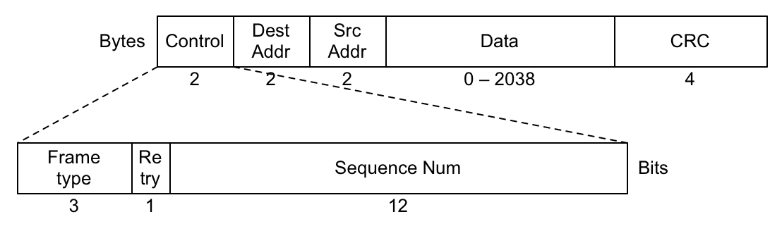
Control Field
- Bits 0-2:
- These three bits describe the frame's type, with the five frame types below currently defined:
000	Data
001	ACK
010	Beacon
100	CTS
101	RTS
- Bit 3:
- This bit is set if the frame is a retransmission.
- Bits 4-15:
- The remaining 12 bits constitute a sequence number (a 12-bit unsigned integer) so that receiving stations can distinguish between and properly order frames. Sequence numbers always start at zero, and wrap back to zero after they reach 212-1.
Addresses
MAC addresses in 802.11~ are unsigned 16-bit integers. The address consisting of all 1's (216-1) is reserved as the broadcast address. Both the destination and source addresses are included in all frame types, for consistency, though Beacon frames use the broadcast address as their destination.
Data
Data frames may carry up to 2038 bytes of data, giving a maximum frame size of 2048 (2K) bytes.
CRC
All frames carry a four-byte CRC checksum, computed using the same polynomial specified in IEEE 802.11. Packets sent from 802.11~ implementations that do not (yet) compute valid checksums should fill the CRC field with 1s (a -1 value). My implementation will accept packets with a -1 CRC value as valid.
802.11~ Interface Routines — Java Versions
See the Java Documentation for more details on the Java code that's provided. The Dot11Interface describes the routines that must be implemented as part of your 802.11~ layer. They're presented briefly below. Note: The RF layer defines a variety of physical-layer constants that your implementation should reference.
int send(short dest, byte[] data, int len);
Send len bytes from data to the address specified in dest. If len exceeds the size of the byte array, send as many bytes as data contains.
int recv(Transmission t);
This function blocks until data arrives, at which point it writes the incoming data and address information into the Transmission instance passed as argument (respecting the size of the byte array in the Transmission) and returns the number of bytes received.
int status();
This function returns a code representing the current status of the 802.11~ layer. The code reflects the most recent error, or the status of the most recent transmission or other operation. Status codes include:
1 | SUCCESS |
Initial value if 802_init is successful |
2 | UNSPECIFIED_ERROR |
General error code |
3 | RF_INIT_FAILED |
Attempt to initialize RF layer failed |
4 | TX_DELIVERED |
Last transmission was acknowledged |
5 | TX_FAILED |
Last transmission was abandoned after unsuccessful delivery attempts |
6 | BAD_BUF_SIZE |
Buffer size was negative |
7 | BAD_ADDRESS |
Pointer to a buffer or address was NULL |
8 | BAD_MAC_ADDRESS |
Illegal MAC address was specified |
9 | ILLEGAL_ARGUMENT |
One or more arguments are invalid |
10 | INSUFFICIENT_BUFFER_SPACE |
Outgoing transmission rejected due to insufficient buffer space |
int command(int cmd, int val);
This function provides a mechanism to pass command or configuration data to an 802.11~ layer at runtime. One could use it to enable or disable debugging output on-the-fly, change system parameters, or prompt the 802.11~ layer to summarize network activity, for example. Note: User-defined command code values should be greater than 10. A compliant 802.11~ implementation must support the following commands:
- Command 0: Options and settings
- Should summarize all command options and report their current settings. The accompanying value parameter is ignored.
- Command 1: Debug level.
- The meaning of non-zero values can be implementation dependent, but passing a value of 0 should disable all debugging output.
- Command 2: Slot selection.
- If the accompanying value parameter is 0 the link layer should select slots randomly. Any other value should cause the link layer to always select
maxCW.
- Command 3: Beacon interval.
- The accompanying value specifies the desired number of seconds between the start of beacon transmissions. A value of -1 should disable the sending of beacon frames.
Project Code:
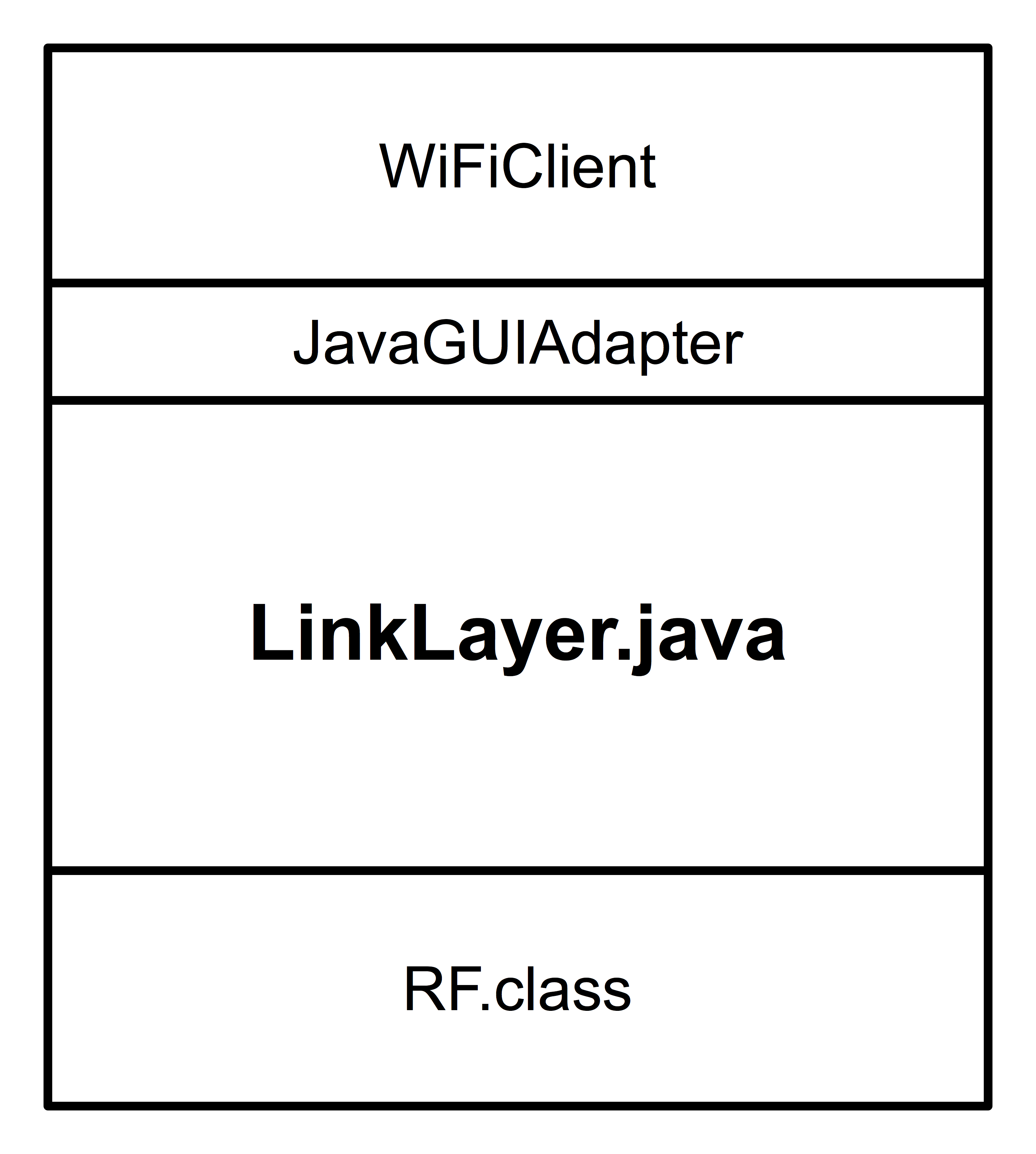
If you're writing in Java, you don't need to know much about the project structure — just implement the 802.11~ interface routines in the LinkLayer class, add any additional classes you need to the wifi package, compile, then run the WiFiClient to test things out. The pieces will end up fitting together like this:
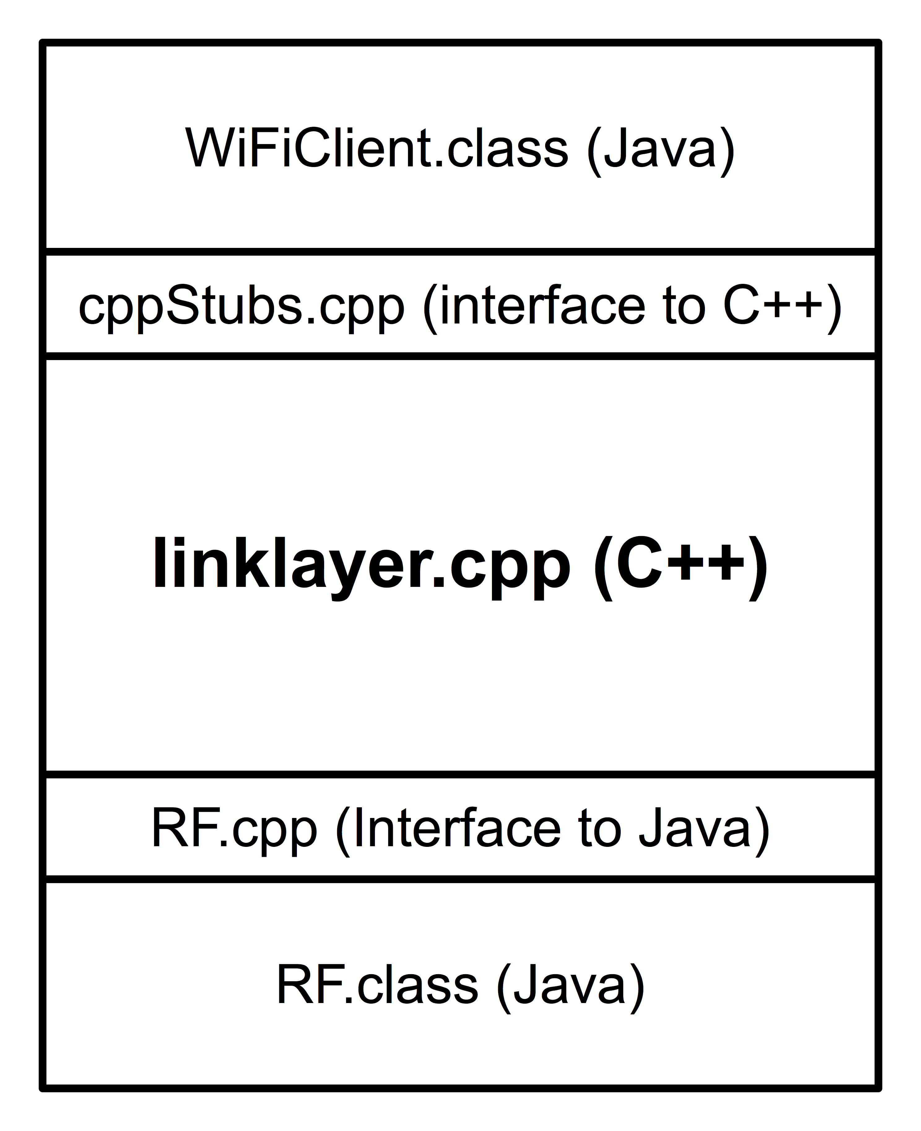
Things get more complex if you implement your layer in C++. The virtual physical layer (RF) is written in Java, as is the client. This means a complete, running 802.11~ project really looks like a "C++ sandwich" — there's a Java layer on top, your C++ code in the middle, and Java again below your code:
The good news is that whether you choose to work in C++ or Java, I'm giving you all you need except for the small matter of the code in LinkLayer, but even there I'm giving you a starting point — a file that compiles with the rest of the project to produce a running program. (The current versions of linklayer.cpp and LinkLayer.java just call the RF layer directly when dot11 interface routines are called.)
Resources:
- Documentation for all Java code I'm supplying.
- Project files are available as an importable Eclipse project or a BlueJ project. You'll need to replace the routines in LinkLayer.java with your own. At the moment, they pretty much do nothing, but at least there's enough there that the whole project compiles and runs. If you insist on using VS Code, this is a reasonable starting point.
- An RF monitor application that understands and displays 802.11~ packets and can help you debug your implementation. It knows
enough about the RF layer to be able to report on transmissions and collisions,
and can wipe out transmissions if you tell it to.
- A working implementation of the project. You can test yours against it as you add functionality to your own.
- You can download a free copy of the 802.11 specification document from this page, or get a copy of the 2012 version here.
- Some helpful diagrams, including the flow chart we went over in class.
Tips:
- Make sure you use a
Packet class! Hide all of those bit-mangling operations so you never have to see them again (after testing them thoroughly, of course.) Make sure you implement a nice toString method (or overload the << operator in C++) so you can print packets easily.
- Use a finite-state diagram to describe the MAC behavior before you start implementing. Be sure it includes details of where and when the collision window is expanded as well as how ACKs are generated and sent.
- When desigining your implementation, think about classes first and then threads — decompose the problem into classes, and then think about which pieces of functionality within a class will need to be implemented in separate threads.
- Use the "nuke" and "jam" settings on the latest version of the monitor to help test your code: Jam can be used to keep the channel busy, and nuke can test how your code responds to collisions.
Grading:
The project will be divided into a series of checkpoints, to help guide your implementation and ensure that no one falls behind. Each of the checkpoints is worth 5% of the overall project grade, and is assessed as either Satisfactory, Unsatisfactory, or F (like midterm grades).
Brad Richards, 2023